Now that you have probably installed the driver for USBasp, it's time that we move on to mount the basic circuit for Atmega328 and get it running on the breadboard. You can get a new Atmega328/P micro-controller or just scavenge one from an Arduino UNO lying around. Before we mount the circuit on breadboard here's the of components that are required.
- Atmega328/P (28 PIN DIP package)
- 22pf Ceramic Capacitors Qty 2 nos.
- 16MHz crystal Qty 1 nos. [have 2-3 in spare just in case the one in use is damaged]
- Tactile Switch/Push Button Qty 1 nos.
- Resistor 10K Ohm Qty 1 nos.
- LED 1 nos.
- Breadboard
- Connecting Wires
The schematic below shows how to configure Atmega328/P on breadboard. I have posted a hand drawn schematic as well as an eagle schematic. Before you mount the circuit lets understand functions of pin that we are using to make a basic circuit of Atmega328/P.
 |
| Configuring Atmega328/P [Click to Open) |
Pin 1 [PC6(RESET/PCI14)]: Pin 1 of Atmega328/p is of multipurpose. We can use it as external reset or as general purpose I/O pin. If RSTDISBL fuse bit
is left unprogrammed, pin 1 can be used as external reset else it can be used as GPIO. In our configuration we will be using it to reset the micro-controller manually.
Pin 7 Vcc: It is used to power the different blocks of micro-controller.
Pin 8 & 22: To ground the circuit and micro-controller.
Pin 9 & 10: These are another multi purpose pins, can be used as GPIO, oscillator o/p and oscillator input. We will be connectiong a 16Mhz Crystal as an external clock source for our Atmega.
Pin 8 & 22: To ground the circuit and micro-controller.
Pin 9 & 10: These are another multi purpose pins, can be used as GPIO, oscillator o/p and oscillator input. We will be connectiong a 16Mhz Crystal as an external clock source for our Atmega.

Pin 20 AVcc: Supply voltage pin for internal ADC modules of Atmega. Should be externally connected to Vcc even if ADC is not in used.
Pin 21 Aref: Analog reference voltage for internal ADC channels of Atmega328.
Pin 21 Aref: Analog reference voltage for internal ADC channels of Atmega328.
Fuse Bits and Setting Them
Fuse bits are used to make basic configuration of any micro-controllers like external reset, clock source, brownout detection, etc. Fuse bits are required to set only once. Atmega328/P has 3 fuse bytes which are required to set.Extended Fuse Byte:
 |
| Extended Fuse Bits and their default values |
High Fuse Byte:
 |
| High Fuse Byte and default values |
The 8 bits are RSTDISBL, DWEN, SPIEN, WDTON, EESAVE, BOOTSZ1, BOTSZ0 & BOOTRST.
Reset Disable(RSTDISBL): This fuse is used to enable or disable external reset from pin 1 on atmega. If external reset is disabled, reset pin can be used as a gpio. By default this bit is left unprogrammed('1') if you want to disable external reset, set this bit to 0.
debugWIRE Enable(DWEN): This fuse is used to enable or disable in circuit debugging feature of Atmel. It is disable or left unprogrammed by default.
SPI Programming Enable(SPIEN): This bit is used to enable or disable programming via SPI interface on Atmega328/P. By default this bit is programmed or set to zero.Watchdog Timer Always On(WDTON): Program this bit to keep watchdog timer always on, by default this bit is left unprogrammed.
EEPROM Save(EESAVE): This bit decides whether the data on eeprom should be erased or not during chip erased cycle. Unprogrammed by default.
Bootloader Size(BOOTSZ0-1): These two bits are used to decide the bootloader size that is to be used on micro-controller.
Boot Reset(BOOTRST): When this bit is programmed the micro-controller will jump to bootloader address on booting.
Note: For Fuse Bits, 1 is Unprogrammed and 0 is Programmed.
Low Fuse Byte:
 |
| Low Fuse Byte and default values |
The 8 bits in this fuse byte are CKDN8, CKOUT, SUT1, SUTO, CKSELx(x = 3-0).
Divide Clock by 8(CKDN8): By default this bit is programmed. This makes atmega328 operate at 1Mhz. We need to disable this fuse to make it operate at internal 8MHz RC osc.
Divide Clock by 8(CKDN8): By default this bit is programmed. This makes atmega328 operate at 1Mhz. We need to disable this fuse to make it operate at internal 8MHz RC osc.
Clock Output(CKOUT): Unprogrammed by default, set to 0 to get clock cycle output.
Start Up time(SUT0-1): To select the start up time for micro-controller.
Select Clock Source(CKSEL0-3): This 4 bit are important to decide the clock source for our micro-controller.
Before we can program or unprogram the fuse of our Atnega we need to interface the USBasp to the micro-controller. Below circuit diagram shows the interfacing of USBasp with Atmega328.
USBasp is available in two types of ICSP connector, 6 Pin & 10 Pin connector. I am using one with 10 Pin Connector. Check your USBasp and make the connections accordingly by referring to the above diagram. Once the USBasp is interfaced with your Atmega328 circuit, make sure all connections are proper and connect the USBasp to your computer.
You can connect an LED between Vcc and Pin 19 SCK as an indicator for connection between your atmega and USBasp.
Now that connections are complete lets move to the software part. On your computer start AVRDUDESS GUI which will give you access to AVRDUDE without using command prompt. You will see lots of option on AVRDUDESS, at the very bottom there's a drop down menu saying 'Select a programmer...' click on it and scroll down to select the option saying USBasp. Once the programmer is selected, click on detect button below 'Select an MCU' drop down menu. Clicking on the detect button will automatically detect the micro-controller you have interfaced with USBasp. If everything is alright, your mcu will be detected in first go without any errors. The LED connected to Vcc and Pin 19 will also flicker when you press the 'Detect' button on AVRDUDESS.
Once the detect button is pressed you should be able to see Detected 'device signature' = AtmegaXXX depending on the MCU you have connected. I have connected Atmega328 so I see the output as 'Detected 1e9514 = Atmega328' where 1e9514 is device signature Atmega328. If you are using Atmega328P device signature will be 1e950F. If you get any error, verify your circuit and connections between USBasp and Atmega.
Now that AVRDUDESS is successfully able to communicate with Atmega328 via USBasp, its time that that we move to configure fuse bits. Since we are just beginning with moving from Arduino to AVR it's better to set fuse bytes as per Atmega328P on Arduino UNO at first and then play around with them as per our requirements. Using AVRDUDESS you can see the current configuration of fuse bits of your Atmega. On the GUI, look for Fuses & Lock Bits section at right of the window. There are two buttons 'Read' and 'Write'. First click on read button. This will read the fuse bytes of your atmega and show the values in hex value inside empty boxes. L for Lower fuse byte, H for Higher fuse byte and e for extended fuse byte.
You can use fuse bit configuration of Arduino UNO for your breadboard mounted Atmega328/P. You can edit the fuse byte value that were read from your MCU or you can use the Bit Selector option just below. Set the new fuse values as followed; L = 0xFF, H = 0xDE, E = 0x05. You can also set H = 0xDA as we will not be using Arduino boot loader.
Once you have edited the values or selected the bits using Bit Selector, click on the 'write' button to write the fuses to your Atmega. If everything is alright, fuses will be set without any problem. If any error occurs in writing fuses, check your circuit and make sure your USBasp is kept at 5V and not 3.3V via small switch or jumper on it.
Now that our Atmega328/P is ready with new configuration lets upload a simple program that will blink the LED that's connected on Pin 19 of Atmega328/P. I have uploaded the hex file for blink program just upload it to the micro-controller by loading the hex file in flash section of AVRDUDESS. Click on ' Program' and your mcu will get programmed to blink the LED at PIN 19.
With this LED blinking, tutorial for setting up basic circuit and configuring fuse bits is completed. In next post I will how did I made the LED blink on Atmega328 using Atmel Studio instead of Arduino IDE. I will make the video tutorial for this post soon. Post your queries or any corrections I need to do in the comments. Thank You!
Start Up time(SUT0-1): To select the start up time for micro-controller.
Select Clock Source(CKSEL0-3): This 4 bit are important to decide the clock source for our micro-controller.
Before we can program or unprogram the fuse of our Atnega we need to interface the USBasp to the micro-controller. Below circuit diagram shows the interfacing of USBasp with Atmega328.
 |
| Interfacing USBasp to Atmega328/P using SPI |
 |
| On breadboard |
Now that connections are complete lets move to the software part. On your computer start AVRDUDESS GUI which will give you access to AVRDUDE without using command prompt. You will see lots of option on AVRDUDESS, at the very bottom there's a drop down menu saying 'Select a programmer...' click on it and scroll down to select the option saying USBasp. Once the programmer is selected, click on detect button below 'Select an MCU' drop down menu. Clicking on the detect button will automatically detect the micro-controller you have interfaced with USBasp. If everything is alright, your mcu will be detected in first go without any errors. The LED connected to Vcc and Pin 19 will also flicker when you press the 'Detect' button on AVRDUDESS.
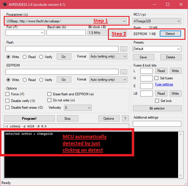 |
| Step for detecting MCU |
Now that AVRDUDESS is successfully able to communicate with Atmega328 via USBasp, its time that that we move to configure fuse bits. Since we are just beginning with moving from Arduino to AVR it's better to set fuse bytes as per Atmega328P on Arduino UNO at first and then play around with them as per our requirements. Using AVRDUDESS you can see the current configuration of fuse bits of your Atmega. On the GUI, look for Fuses & Lock Bits section at right of the window. There are two buttons 'Read' and 'Write'. First click on read button. This will read the fuse bytes of your atmega and show the values in hex value inside empty boxes. L for Lower fuse byte, H for Higher fuse byte and e for extended fuse byte.
 |
| Read fuses |
 |
| Fuse values from MCU |
If you have a brand new atmega328/p then you will get the fuse vales as per the default factory setting as we saw earlier [L = 0x62 H = 0xD9 E = 0x0F7]. If you have extracted your Atmega from some circuit, fuse bit will be already configured. If the atmega328/p is from some old arduino board then you are not reconfigure the fuse bits of your atmega, if you want you can play around with certain fuse bits like BODLEVEL, BOOTRST, BOOTSZ and Low Fuse Byte if you are sure about what you are doing. Make sure you are being careful and DON'T MESS UP WITH FUSE BIT RSTDISBL, SPIEN, and LOCK BITS you might brick or lock down your micro-controller.
 |
| Edit fuse vales or load preset values |
 |
| Write the fuse bytes |
 |
| Load the blinky.hex file and click program |
 | |||
| Program uploaded to mcu and successfully verified |
 | |||||
| LED will blink at interval of 1 second |
Download Blink.hex
With this LED blinking, tutorial for setting up basic circuit and configuring fuse bits is completed. In next post I will how did I made the LED blink on Atmega328 using Atmel Studio instead of Arduino IDE. I will make the video tutorial for this post soon. Post your queries or any corrections I need to do in the comments. Thank You!
Comments
Post a Comment